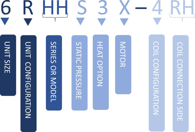
HH Series

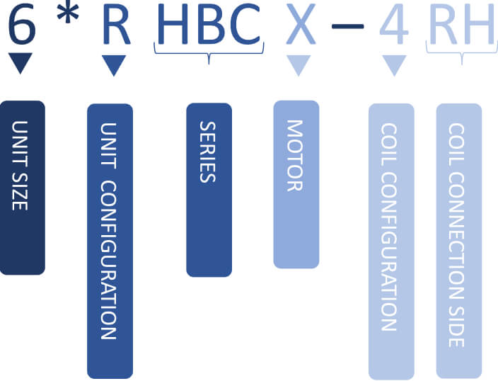
HBC Series

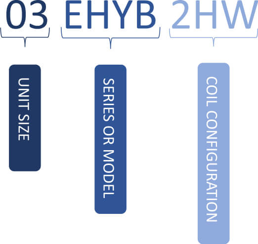
HYB Series

NOTE:
Not all descriptors may appear for each model. See individual product specification documents for complete model number configuration options
Glossary
| Section | Digit Codes | Description |
|
Coil Configuration |
3-2 Pipe, 3 Row 4-2 Pipe 4 Row |
A 2-pipe system has one pipe for hot water supply and one for return, and can provide heating or cooling at any given time depending on the water source. A 4-pipe system has two separate pipes for hot water and two for chilled water allowing for simultaneous heating and cooling in different zones of a building. Multiple rows of tubes increase the coil’s surface area allowing it to transfer more heat to the air passing over the coil. |
|
Coil Connection Side |
LH–Left Hand RH–Right Hand |
The hot water supply should be connected to the bottom connection of the coil on one side. Please select which side of the unit you prefer the coil connection. |
|
Heat Option |
KW Heat |
A higher kW in HVAC indicates more capacity for heating or cooling, but it must be matched with the specific requirements of the space and considered alongside efficiency ratings to ensure optimal performance and energy consumption. |
|
Motor Type |
0–PSC X–ECM |
Permanent Split Capacitor motors run at a fixed speed and operate at full power regardless of the demand for heating or cooling. Electronically Commutated Motors are a type of variable speed motor with built-in inverters and microprocessors that adjust speed based on demand. |
|
Series |
HH, HHX HBC, HBCX, PHBC, RHBC, CHBC HYB, PHYB |
Name of product family or model name |
|
Static Pressure |
0–Standard to High Static S–Low Static Model |
Static pressure is the amount of pressure required to overcome static created by external objects such as ductwork, grilles, etc. The Low Static Model is designed for ductless applications. |
|
Unit Configuration |
0–Open Blower P–Return Air Plenum R–Recessed, Telescoping Panel C–Cabinet Exposed |
Ceiling Fan Coils can be configured to accommodate placement in the installation point. See specification document for physical dimensions and renders of each option. |
|
Unit Size |
CFM |
An air-conditioner’s unit size or nominal capacity is the output level it can handle when functioning in either cooling or heating mode. Cubic feet per minute (CFM) measures how much airflow volume passes through a space in a minute. |
|
Voltage |
120 / 1Ph /60Hz 230 / 1Ph / 60Hz 265 / 1Ph / 60Hz |
Voltage is the electrical pressure that pushes an electric current through a circuit. Higher voltageindicates a more powerful pressure. Most HVAC systems use with 115 (120)V or 230V depending onsize and capacity. |
